In electronics manufacturing, the cost of a bad solder joint is almost never paid on the day it is made.
A cold joint, an incomplete fillet or a slightly overheated pad can pass visual inspection, leave the factory, and only show up later as an intermittent failure in a customer’s product. By then the board is buried inside an assembly, the batch is shipped, and the cost has multiplied into rework, warranty claims or lost trust.
That is the quiet problem robotic soldering is designed to solve. Not simply “faster soldering”, but making the soldering process controlled, repeatable and measurable before the assembly leaves the cell.
At ICA we design and build robotic soldering cells around the actual board and process. ICA designs and builds robotic automation systems for Screwing, Soldering and Dispensing applications. Below is what typically happens from the moment a PCB or module enters the cell until a verified assembly comes out the other side.
The process journey inside a robotic soldering cell
Think of the cell as a short, tightly controlled production story. Each step exists for a reason — and each one reduces a specific risk that manual soldering leaves open.
1. Component / PCB Entry
The board or module is presented to the cell — either by conveyor, by operator loading a fixture, or by a previous upstream process. The fixture is designed for the specific part so that the soldering points sit in known, repeatable positions. Good fixturing is not a detail; it is the foundation of everything that follows. If the board can shift, the robot’s accuracy is wasted.
2. Part Presence & Position Detection
Before the robot moves, the cell confirms that the correct part is present and seated. Sensors or a vision system check presence and, where needed, fine position. This step prevents the robot from attempting to solder an empty nest or a misloaded board — a simple error that is surprisingly common on manual lines when operators are under time pressure.
3. Robot Positioning
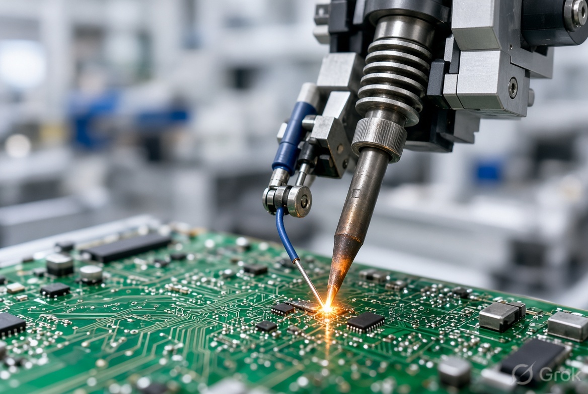
The robot (typically a SCARA or 6-axis arm) moves the soldering iron or soldering head to the first programmed point. Motion is point-to-point and fully programmable, so the path, approach angle and dwell can be set for each joint type on the board. Once taught and validated, the same path is repeated every cycle, every shift — independent of operator fatigue or changeover.
4. Automatic Solder Wire Feeding
Solder wire is fed automatically in a controlled length and at a controlled rate. This removes two common sources of variation in manual work: inconsistent wire volume and inconsistent timing between heat application and solder delivery. The right amount of solder arrives at the right moment, which is essential for forming a proper fillet without excess or starvation.
5. Temperature-Controlled Soldering
The soldering tip temperature is actively controlled and monitored. Too cold and you risk a cold joint; too hot and you risk pad damage or component stress. Closed-loop temperature control keeps the process inside the process window that the board and components can tolerate. This is the single biggest difference between a trained operator on a good day and a process that is stable every day.
6. Joint Inspection (CCD / Vision)
After soldering (or in selected cells, during the cycle), a CCD camera or vision system inspects the joint. Presence of solder, basic fillet shape and obvious defects can be checked against acceptance criteria. Boards that fail can be flagged or diverted before they move further down the line. This is not a substitute for a full AOI system in every case, but it catches the clear process escapes that would otherwise become field failures.
7. Smoke Extraction & Operator Safety
Soldering fumes are extracted at source. Integrated fume extraction protects operators and keeps the work area cleaner — an often overlooked but practical part of running a soldering process at production volumes without creating a secondary health or housekeeping problem.
8. Completed Board / Module Output
The finished assembly leaves the cell. Depending on the line design, it may go to the next process, to a buffer, or to final inspection. Because each critical parameter (temperature, feed, motion, inspection result) was controlled and, where required, recorded, the quality of the joint is no longer an assumption based on sampling — it is the result of a closed process.
Why this sequence reduces cold joints and rejection
Manual soldering quality depends heavily on the operator’s skill, attention and consistency across a shift. Even good operators vary. A robotic cell does not eliminate the need for process engineering — it makes the engineered process repeatable.
In practical terms:
- Temperature control keeps every joint inside the thermal process window.
- Controlled wire feed reduces volume variation that leads to weak or excessive joints.
- Programmable motion removes path and dwell variation between operators and shifts.
- Vision inspection catches clear defects before the board moves on.
- Traceability options (when integrated) allow later investigation if a field issue ever appears.
The result is not “perfect soldering forever”. It is a process whose variation is understood, controlled and low enough that rejection rates and field returns drop measurably.
Where robotic soldering fits best
We typically see the strongest return in:
- PCB assembly and through-hole or selective soldering points that are repetitive
- Electronic modules and power assemblies
- Wiring harnesses and connector soldering
- Sensor manufacturing and other products where joint reliability is critical to field performance
It is less about replacing every human solderer and more about protecting the joints that carry the highest quality or warranty risk.
How we approach the cell at ICA
A robotic soldering cell is only as good as its integration. We design the fixture, select and program the robot, integrate wire feeding and temperature control, add vision where it adds real value, and arrange fume extraction so the cell is practical to run. The same team that designs the cell also builds and commissions it from our facilities in Chennai and Coimbatore.
You can explore related solutions on our robotic automation page and the broader products overview. Vision support is covered under vision systems.
A practical next step
If rejection rates or field returns on soldered joints are a recurring concern, the most useful starting point is not a brochure. It is a conversation about the actual board, the current process, and where the defects are appearing.
Share a sample board or a short description of the joints that cause the most trouble. We can then discuss whether a robotic soldering cell is the right response — and what the process would look like for your part.
That is usually more productive than comparing feature lists.